Home
AC103-6
AC103-7
Accident Reporting
AIM
AeroMedical
Airport Security
Airport Markings
Annual Inspection
ASTM
Board Members
Contact NAPPF
Density Altitude
Endorsements
Flight Parks
Flight
Instruction
Flight
Instruments
Flight Plan
Formation Flying
Hints
History
Home
Insurance
Knowledge Test
LINKS
Light
Sport Aircraft Process
NAPPF UPDATE
Navigation
News
NOTAM
NPRM
Pilot
Privileges & Limitations
Pilot/Instructor Requirements
Part 103
Part 103 Preamble
Radio
Resources
Sectional Charts
Sport
Pilot Topics
TFR
Training
Training Materials
UltraFlight
Magazine
UltraFlight Radio
Visibility & Cloud
Clearance
Visual Approach Slope Indicator (VASI)
Weather
Weather Services
Home
NAPPF
Flight Instruments
Altimeter

The pressure altimeter is
simply an aneroid barometer that measures the pressure of the atmosphere at the
level where the altimeter is located, and presents an altitude indication in
feet. The altimeter uses static pressure as its source of operation. Air is more
dense at the surface of the Earth than aloft, therefore as altitude increases,
atmospheric pressure decreases. This difference in pressure at various levels
causes the altimeter to indicate changes in altitude.
The dial of a typical altimeter is graduated with numerals arranged clockwise
from 0 to 9 inclusive. The shortest hand indicates altitude in tens of thousands
of feet; the intermediate hand in thousands of feet; and the longest hand in
hundreds of feet, subdivided into 20-foot increments.
Altitude
Altitude is vertical distance above some point or level used as a reference.
There may be as many kinds of altitude as there are reference levels from which
altitude is measured and each may be used for specific reasons. Pilots are
usually concerned, however, with five types of altitudes:
Absolute Altitude
The vertical distance of an aircraft above the terrain.
Indicated Altitude
That altitude read directly from the altimeter (uncorrected) after it is set
to the current altimeter setting.
Pressure Altitude
The altitude indicated when the altimeter setting window (barometric scale)
is adjusted to 29.92. This is the standard datum plane, a theoretical plane
where air pressure (corrected to 15° C) is equal to 29.92 in. Hg. Pressure
altitude is used for computer solutions to determine density altitude, true
altitude, true airspeed, etc.
True Altitude
The true vertical distance of the aircraft above sea level—the actual
altitude. (Often expressed in this manner; 10,900 feet MSL.) Airport, terrain,
and obstacle elevations found on aeronautical charts are true altitudes.
Density Altitude
This altitude is pressure altitude corrected for nonstandard temperature
variations. When conditions are standard, pressure altitude and density altitude
are the same. Consequently, if the temperature is above standard, the density
altitude will be higher than pressure altitude. If the temperature is below
standard, the density altitude will be lower than pressure altitude. This is an
important altitude because it is directly related to the aircraft’s takeoff and
climb performance.
Airspeed Indicator
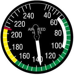
The airspeed indicator is a sensitive, differential pressure gauge which
measures and shows promptly the difference between (1) pitot, or impact
pressure, and (2) static pressure, the undisturbed atmospheric pressure at level
flight. These two pressures will be equal when the aircraft is parked on the
ground in calm air. When the aircraft moves through the air, the pressure on the
pitot line becomes greater than the pressure in the static lines. This
difference in pressure is registered by the airspeed pointer on the face of the
instrument, which is calibrated in miles per hour (MPH), knots, or both.
Airspeeds
Indicated Airspeed
Indicated airspeed (IAS) is the direct instrument reading obtained from the
airspeed indicator, uncorrected for variations in atmospheric density,
installation error, or instrument error.
Calibrated Airspeed
Calibrated airspeed (CAS) is indicated airspeed corrected for installation error
and instrument error.
True Airspeed
The true airspeed indicator (TAS) is calibrated to indicate true airspeed under
standard sea level conditions—that is, 29.92 in. Hg. and 15° C.
Airspeed Indicator Markings
The following is a description of the standard color-code markings on airspeed
indicators used on single-engine light airplanes:
White Arc
FLAP
OPERATING RANGE
Lower limit of the White Arc
POWER-OFF STALLING SPEED WITH THE WING FLAPS AND
LANDING GEAR IN THE
LANDING POSITION
Upper limit of the White Arc
MAXIMUM FLAPS EXTENDED SPEED
Green Arc
NORMAL OPERATING RANGE
The lower limit of the Green Arc
POWER-OFF STALLING SPEED WITH THE WING FLAPS AND
LANDING GEAR RETRACTED
Upper limit of the Green Arc
MAXIMUM STRUCTURAL CRUISING SPEED
Yellow Arc
CAUTION RANGE (the yellow arc)
Red Line
NEVER-EXCEED SPEED (the red line)
Other Airspeed Limitations
There are other important airspeed limitations not marked on the face of the
airspeed indicator. These speeds are generally found on placards in view of the
pilot and in the Airplane Flight Manual or Pilot’s Operating Handbook.
The following are abbreviations for performance speeds:
VA
design maneuvering speed.
VFE
maximum flap extended speed.
VNE
never-exceed speed.
VS
the stalling speed or the minimum steady flight speed at
which the airplane is
controllable.
VS0
the stalling speed or the minimum steady flight speed in
the landing configuration.
VS1
the stalling speed or the minimum steady flight speed
obtained in a specified
configuration.
VX
speed for best angle of climb
VY
speed for best rate of climb
Vertical Speed Indicator

The vertical speed indicator (VSI) or vertical velocity indicator indicates
whether the aircraft is climbing, descending, or in level flight. The rate of
climb or descent is indicated in feet per minute. If properly calibrated, this
indicator will register zero in level flight.
Pitot – Static System
THE PITOT-STATIC SYSTEM AND ASSOCIATED
INSTRUMENTS

In this system, the impact
air pressure (air striking the airplane because of its forward motion) is taken
from a pitot tube, which is mounted either on the leading edge of the wing or on
the nose, and aligned to the relative wind. On certain aircraft, the pitot tube
is located on the vertical stabilizer. These locations provide minimum
disturbance or turbulence caused by the motion of the airplane through the air.
The static pressure (pressure of the still air) is usually taken from the static
line attached to a vent or vents mounted flush with the side of the fuselage.
Airplanes using a flush-type static source, with two vents, have one vent on
each side of the fuselage. This compensates for any possible variation in static
pressure due to erratic changes in airplane attitude.
The openings of both the pitot tube and the static vent should be checked during
the preflight inspection to assure that they are free from obstructions. Clogged
or partially clogged openings should be cleaned by a certificated mechanic.
Blowing into these openings is not recommended because this could damage any of
the three instruments.
Magnetic Compass
The magnetic compass, which is the only direction-seeking instrument in the
airplane, is simple in construction. It contains two steel magnetized needles
fastened to a float around which is mounted a compass card. The needles are
parallel, with their north-seeking ends pointed in the same direction. The
compass card has letters for cardinal headings, and each 30° interval is
represented by a number, the last zero of which is omitted. For example, 30°
would appear as a 3 and 300° would appear as 30. Between these numbers, the card
is graduated for each 5°.
The float assembly is housed in a bowl filled with acid-free white kerosene. The
purposes of the liquid are to dampen out excessive oscillations of the compass
card and relieve by buoyancy part of the weight of the float from the bearings.
Jewel bearings are used to mount the float assembly on top of a pedestal. A line
(called the lubber line) is mounted behind the glass of the instrument that can
be used for a reference line when aligning the headings on the compass card.
Variation
Although the magnetic field of the Earth lies roughly north and south, the
Earth’s magnetic poles do not coincide with its geographic poles, which are used
in the construction of aeronautical charts. Consequently, at most places on the
Earth’s surface, the direction-sensitive steel needles which seek the Earth’s
magnetic field will not point to True North but to Magnetic North. The angular
difference between True North and the direction indicated by the magnetic
compass—excluding deviation error—is variation. Variation is different for
different points on the Earth’s surface and is shown on the aeronautical charts
as broken lines connecting points of equal variation. These lines are isogonic
lines. The line where the magnetic variation is zero is an agonic line.
Deviation
Actually, a compass is very rarely influenced solely by the Earth’s magnetic
lines of force. Magnetic disturbances from magnetic fields produced by metals
and electrical accessories in an aircraft disturb the compass needles and
produce an additional error. The difference between the direction indicated by a
magnetic compass not installed in an airplane, and one installed in an airplane,
is deviation.
Although compensating magnets on the compass are adjusted to reduce this
deviation on most headings, it is impossible to eliminate this error entirely on
all headings. Therefore, a deviation card, installed in the cockpit in view of
the pilot, enables the pilot to maintain the desired magnetic headings.
Using the Magnetic Compass
Since the magnetic compass is the only direction-seeking instrument in most
airplanes, the pilot must be able to turn the airplane to a magnetic compass
heading and maintain this heading. It will help to remember the following
characteristics of the magnetic compass which are caused by magnetic dip. These
characteristics are only applicable in the Northern Hemisphere. In the Southern
Hemisphere the opposite is true.
If on a northerly heading and a turn is made toward east or west, the initial
indication of the compass lags or indicates a turn in the opposite direction.
This lag diminishes as the turn progresses toward east or west where there is no
turn error.
If on a southerly heading and a turn is made toward the east or west, the
initial indication of the compass needle will indicate a greater amount of turn
than is actually made. This lead also diminishes as the turn progresses toward
east or west where there is no turn error.
If a turn is made to a northerly heading from any direction, the compass
indication when approaching north lags behind the turn. Therefore, the rollout
of the turn is made before the desired heading is reached.
If a turn is made to a southerly heading from any direction, the compass
indication when approaching southerly headings leads behind the turn. Therefore,
the rollout is made after the desired heading is passed. The amount of lead or
lag is maximum on the north-south headings and depends upon the angle of bank
used and geographic position of the airplane with regard to latitude.
When on an east or west heading, no error is apparent while entering a turn to
north or south; however, an increase in airspeed or acceleration will cause the
compass to indicate a turn toward north; a decrease in airspeed or acceleration
will cause the compass to indicate a turn toward south.
If on a north or south heading, no error will be apparent because of
acceleration or deceleration.
The magnetic compass should be read only when the aircraft is flying straight
and level at a constant speed. This will help reduce errors to a minimum.
If the pilot thoroughly understands the errors and characteristics of the
magnetic compass, this instrument can become the most reliable means of
determining headings.
Resources:
Pilot's Handbook Of Aeronautical Knowledge
AC 61-23C Revised 1997